
LogicSim

This Logic Gate Simulator is developed using Unity and is designed for educational purposes, helping users understand the basics of digital logic circuits.

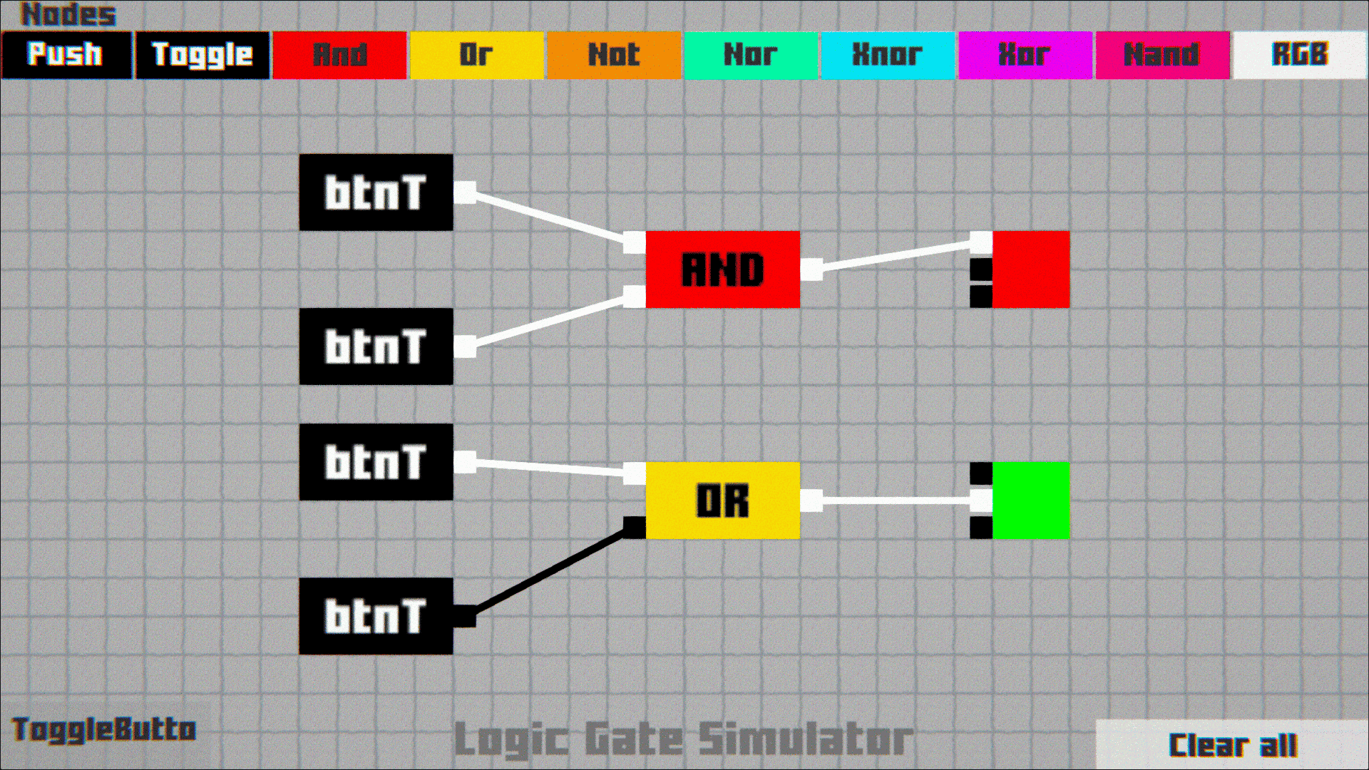
- Click on a gate to drag and place it on the workspace.
- Click on the floor beneath a placed gate to delete it.
- Scroll Mouse by holding Right-click anywhere on the workspace to zoom in/out.
- Click the “Clear All” button to remove the entire schematic.
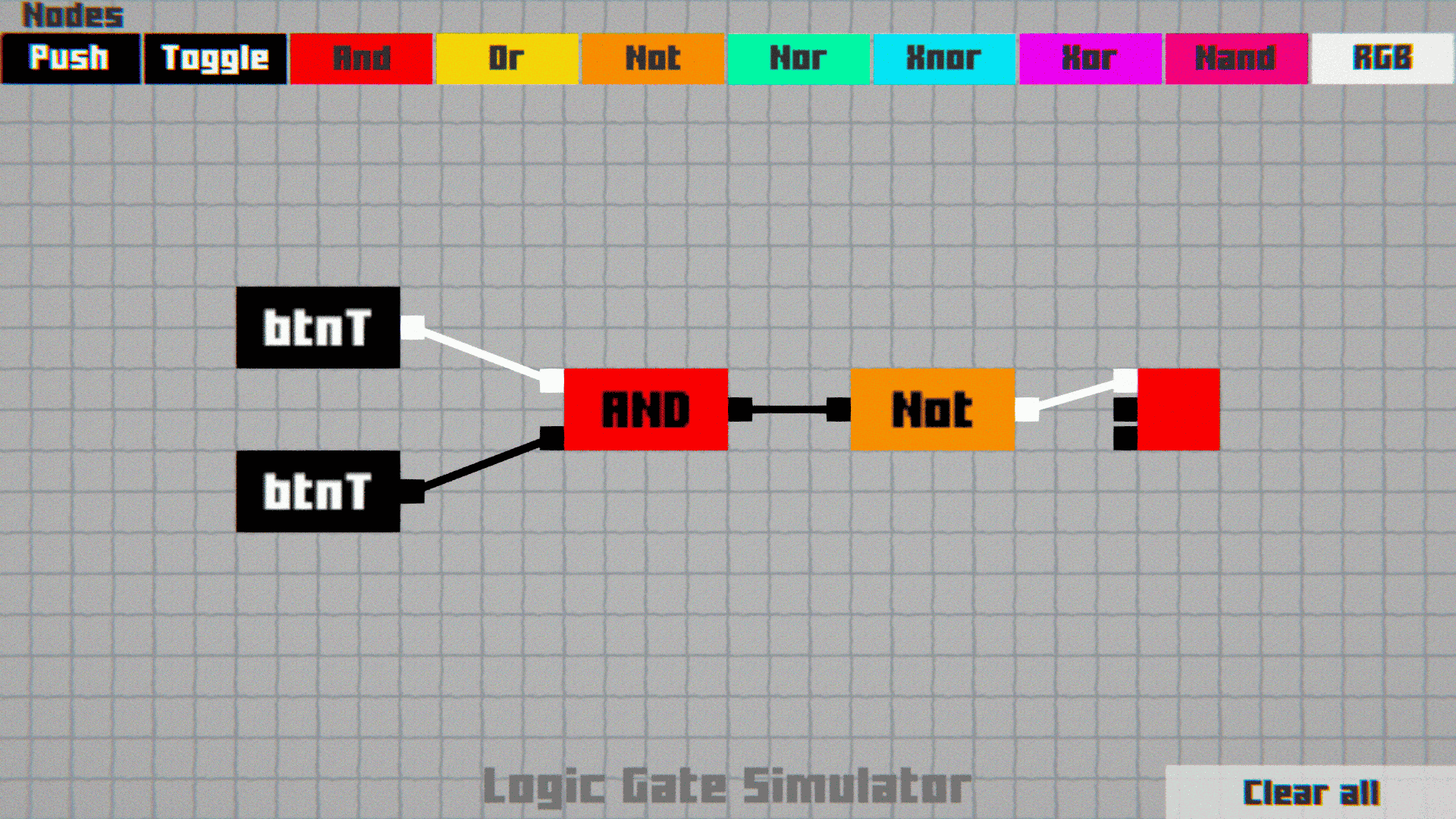
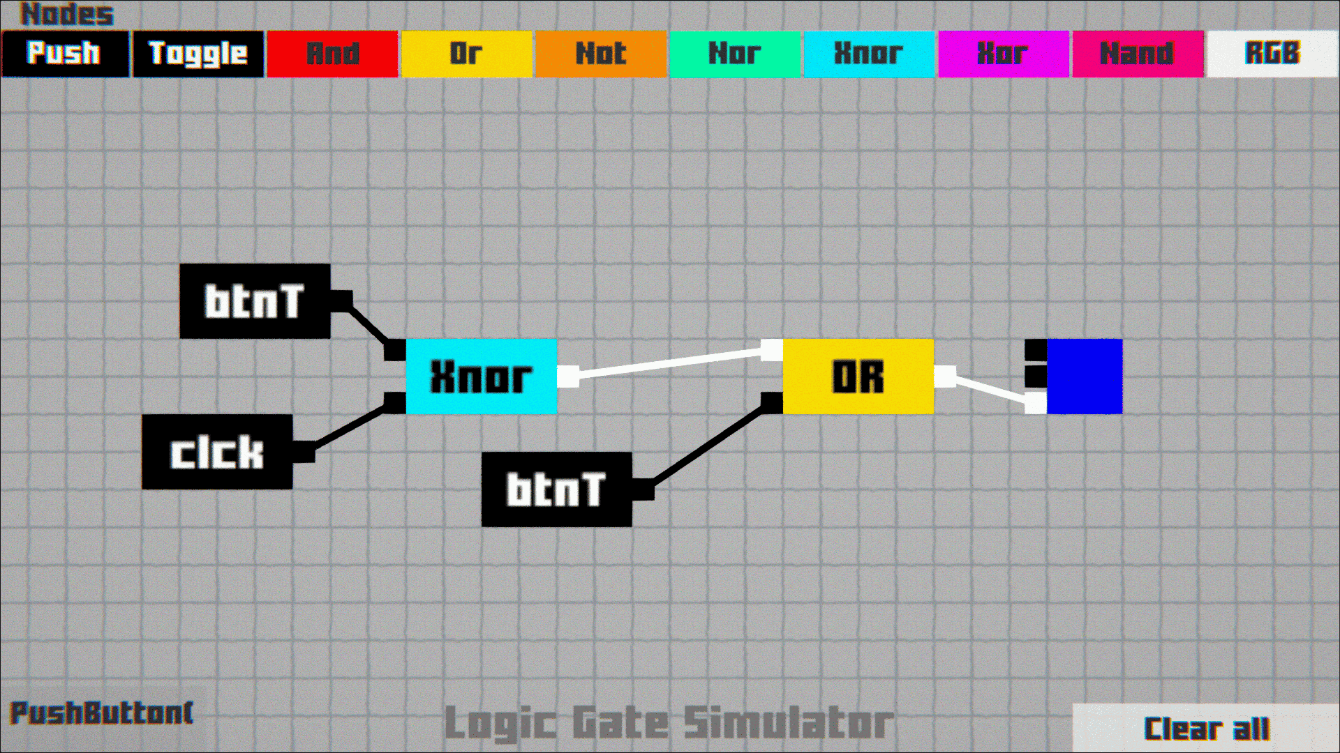
- Click on a node (input or output) of any gate to begin drawing wires.

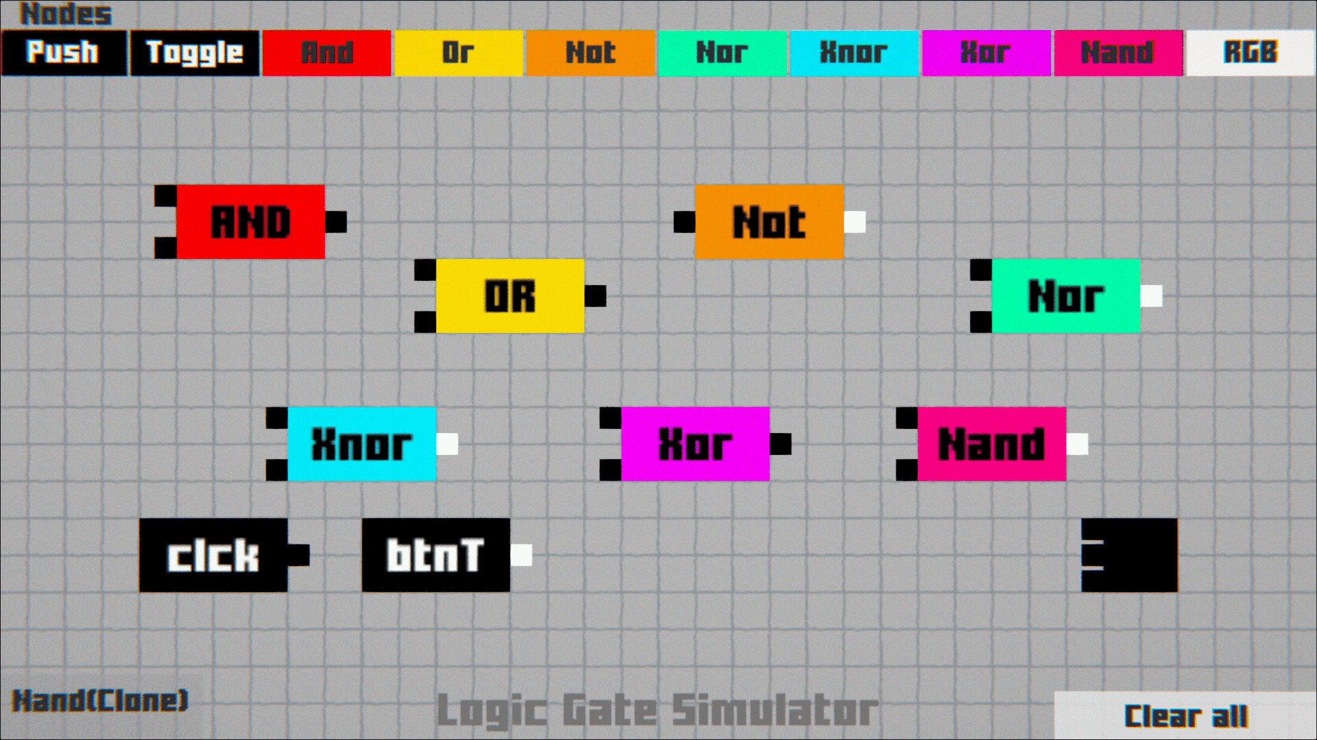
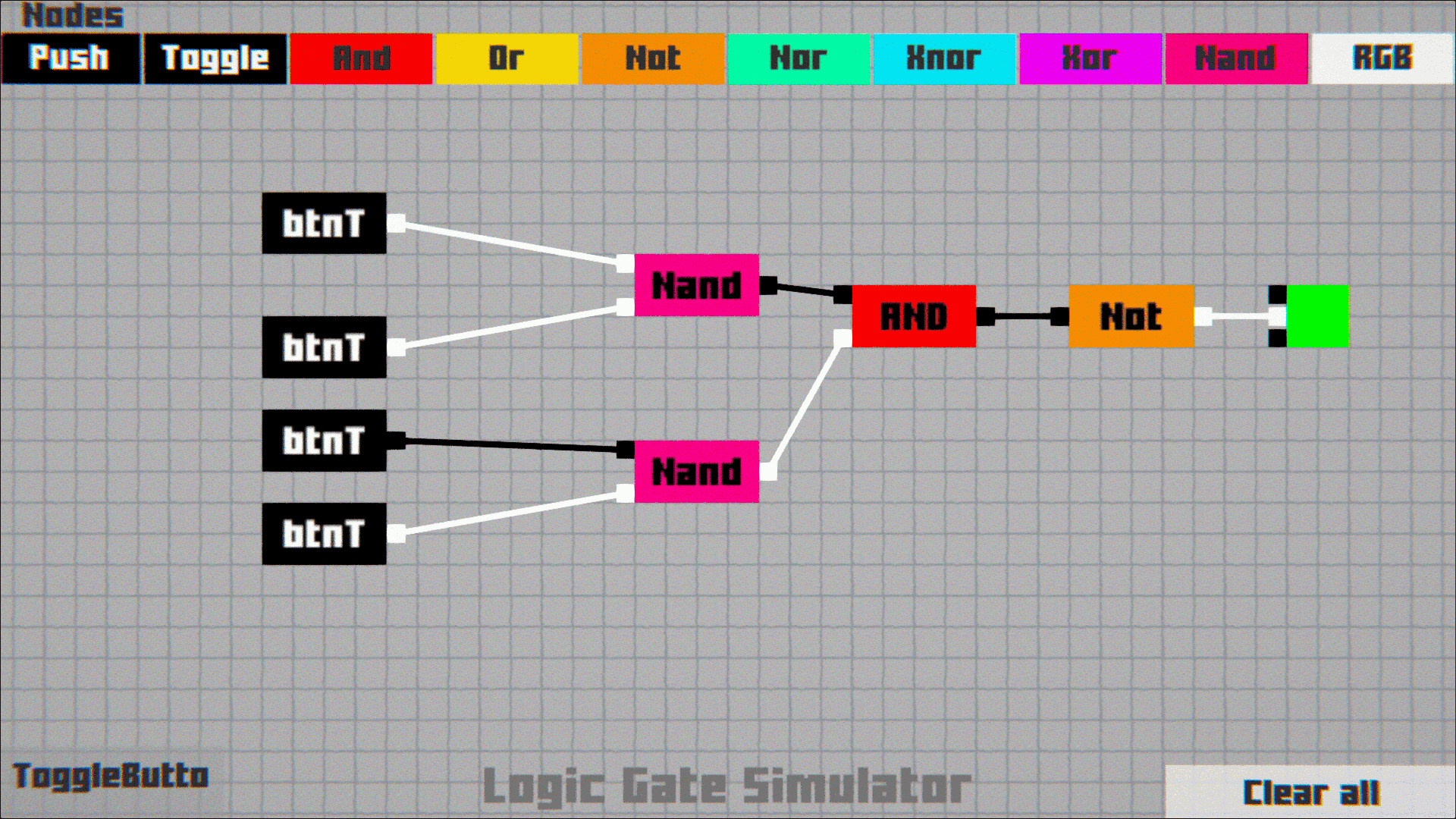
The simulation includes the following logic gates and components:
Inputs:PUSH BUTTON, TOGGLE BUTTON
Logic Gates:
AND, OR, NOT, NAND, NOR, XOR, XNOR
Output:
RGB (used as an output indicator)

Built on an existing open-source project, this simulator remains open-source, credits the original authors, and includes modifications to improve usability and accessibility for developers and learners.
Source Code : Parven05/LogicSim: Simple logic Gate Simulator
Leave a comment
Log in with itch.io to leave a comment.